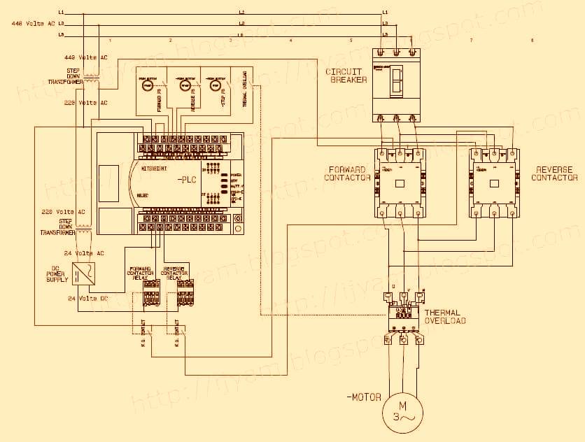
Wiring Diagram For 3 Phase Motor Control
The wiring diagram above is similar to the ones shown earlier. 2-Phase and 3-Phase Size 00 to 5 44 3-Phase Size 6 45 3-Phase Size 7 46. Pin On Non Stop Engineering When we press the start button the current flows through the contactor coil magnetizing coil and control. Wiring Diagram For 3 Phase Motor Control . The working principle of a DOL starter begins with the connection to the 3-phase main with the motor. Electrical wiring is an electrical installation of cabling and associated devices such as switches distribution boards sockets and light fittings in a structure. To energise the four coils of the stepper motor we are using the digital pins 8910 and 11. Magnetic Motor Starter for Electric Motor Control 5HP 18amp 3-phase 208-240VAC with Adjustable Overload Relay 12 TO 18 AMPS 5 6690 66. One switch connects or disconnects the white wire on the bottom terminal. 90 FREE delivery Tue Jul 13. In the above one phase motor wiring i first connect a 2 pole circuit bre...

